What Are You Looking For?
Rubber Magnets in Motor Applications – Technical Support (Ferrite vs. NdFeB)
1. Overview: Why Use Rubber Magnets in Motors?
In micro DC motors, stepper motors, synchronous motors, sensors and encoders, rubber magnets (flexible magnets) are often used as rotor poles or stator rings. Compared with sintered ferrite or sintered NdFeB magnetic tiles, rubber magnets offer the following key advantages:
The two most common rubber magnet materials for motor applications are Ferrite Rubber Magnets and NdFeB Rubber Magnets. Their performance differs significantly, making them suitable for different motor grades.
2. Comparison of the Two Rubber Magnet Materials (Motor‑Specific)
| Property | Ferrite Rubber Magnet | NdFeB Rubber Magnet |
|---|---|---|
| Max. energy product (BH)max | 8.8 – 13.6 kJ/m³ (1.1 – 1.7 MGOe) anisotropic grade | 44 – 96 kJ/m³ (5.5 – 12.0 MGOe) production grade |
| Remanence Br | 210 – 270 mT (anisotropic) | 550 – 800 mT (isotropic / anisotropic) |
| Coercivity HcB | 151 – 179 kA/m | 285 – 478 kA/m |
| Intrinsic coercivity HcJ | 148 – 319 kA/m | 600 – 876 kA/m |
| Recommended operating temperature | -40°C ~ +80°C | -40°C ~ +120°C (some grades up to +150°C) |
| Density | 3.6 – 3.8 g/cm³ | 5.5 – 6.2 g/cm³ |
| Hardness | 65 – 85 Shore A | 30 – 60 Shore D |
| Tensile strength | 3.8 – 6.9 MPa | ≥ 3.8 MPa |
| Elongation at break | 50 – 80% | ≥ 55% |
| Cost | Low | Medium (approx. 3‑5× ferrite rubber magnet) |
| Typical motor types | Low‑cost DC motors, toy motors, fan motors, door‑lock motors | High‑power‑density DC motors, automotive motors, precision servos, encoders |
💡 Key conclusion:
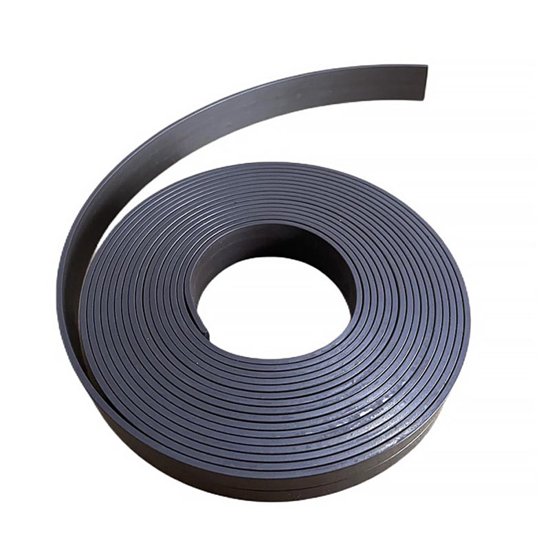
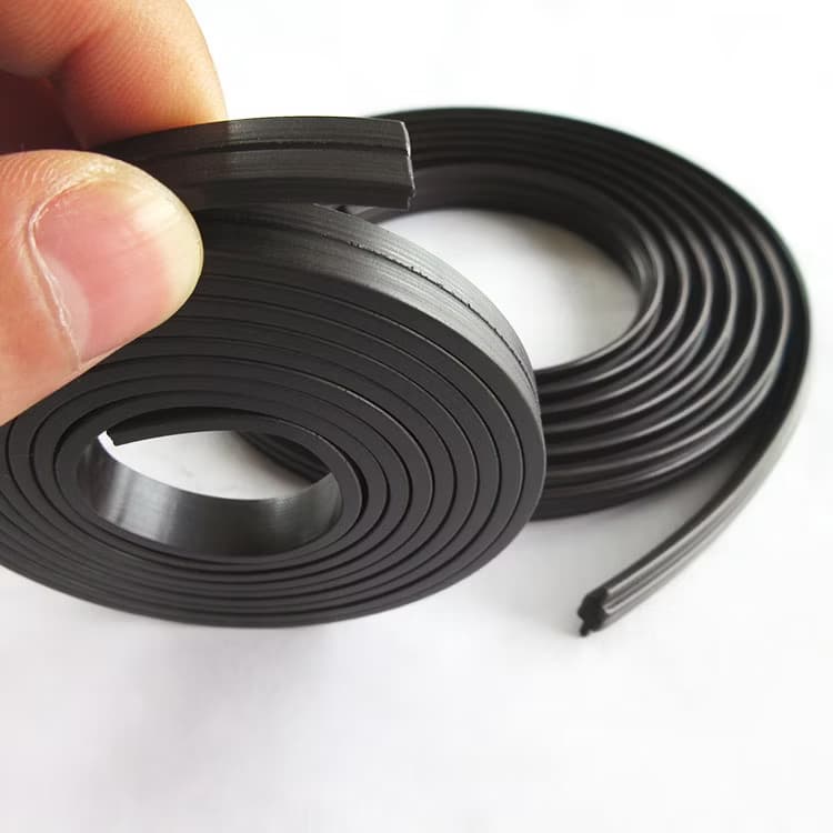
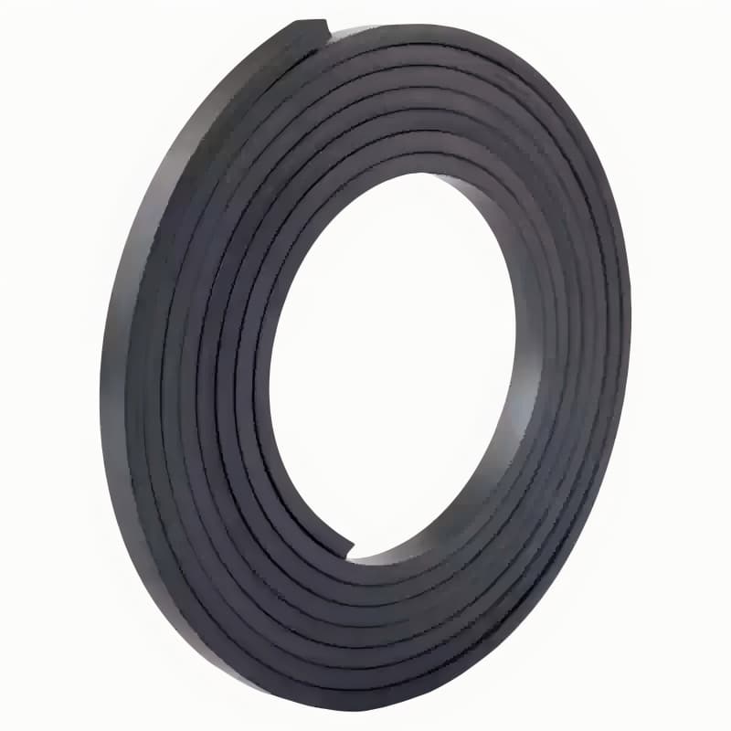
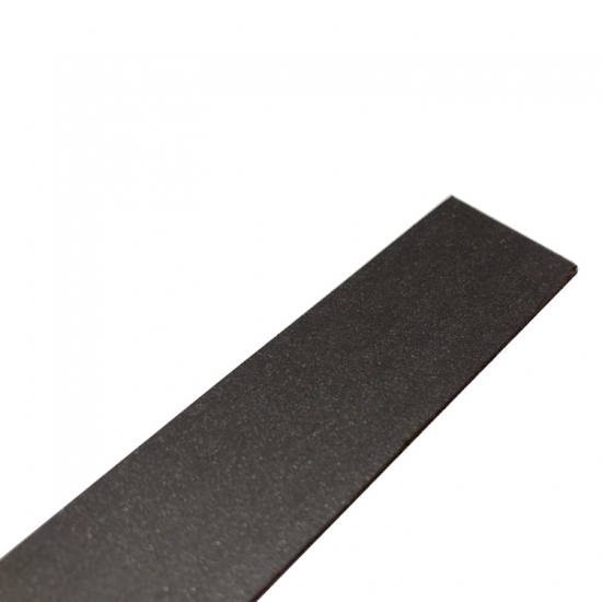
3. Typical Forms of Rubber Magnets in Motors
Rubber magnets are used in motors in the following typical forms:
| Form | Description | Common motor types |
|---|---|---|
| Multi‑pole strip | Long strip with alternating poles along its length, bonded to the rotor core surface | Micro DC motors, stepper motors |
| Magnet ring | Circular ring, radially or axially multi‑pole magnetized | BLDC motors, sensor encoders |
| Magnet segment / tile | Arc or square die‑cut pieces, assembled around the rotor | Automotive motors, power tool motors |
| Extruded profile | Special cross‑section that fits directly into rotor slots | Home appliance motors |
4. Selection Guide for Motor Design
4.1 Selection by Motor Power and Torque
| Motor type | Recommended material | Typical thickness | Pole count | Notes |
|---|---|---|---|---|
| Toy motor (low torque) | Ferrite rubber magnet | 1.0 – 1.5 mm | 2 / 4 poles | Cost priority |
| Fan motor | Ferrite rubber magnet | 1.5 – 2.0 mm | 4 / 6 poles | Medium torque |
| Car door‑lock motor | NdFeB rubber magnet | 1.0 – 1.5 mm | 2 / 4 poles | Small size, high torque |
| Electric mirror motor | NdFeB rubber magnet | 0.8 – 1.2 mm | 2 poles | Precision control |
| Power tool motor (some) | NdFeB rubber magnet | 1.5 – 2.5 mm | 4 / 6 poles | High power density |
| BLDC sensor / encoder | NdFeB rubber magnet | 1.0 – 2.0 mm | 8 – 24 poles | High signal accuracy |
4.2 Selection by Operating Temperature
4.3 Selection by Demagnetization Resistance
5. Technical Specification Comparison Table (Motor‑Specific, Verified Data)
| Parameter | Ferrite Rubber Magnet (anisotropic grade) | NdFeB Rubber Magnet (production grade) |
|---|---|---|
| Remanence Br (T) | 0.21 – 0.27 | 0.55 – 0.80 |
| Coercivity HcB (kA/m) | 151 – 179 | 285 – 478 |
| Intrinsic coercivity HcJ (kA/m) | 148 – 319 | 600 – 876 |
| Max. energy product (BH)max (kJ/m³) | 8.8 – 13.6 | 44 – 96 |
| Max. energy product (MGOe) | 1.1 – 1.7 | 5.5 – 12.0 |
| Density (g/cm³) | 3.6 – 3.8 | 5.5 – 6.2 |
| Hardness | 65 – 85 Shore A | 30 – 60 Shore D |
| Tensile strength (MPa) | 3.8 – 6.9 | ≥ 3.8 |
| Elongation at break (%) | 50 – 80 | ≥ 55 |
| Recommended operating temperature (°C) | -40 ~ +80 | -40 ~ +120 (some +150) |
| Temperature coefficient of Br (%/°C) | -0.2 ~ -0.3 | -0.07 ~ -0.13 |
| Multi‑pole pitch accuracy | ±0.1 mm | ±0.1 mm (precision ±0.05 mm) |
| Maximum thickness (mm) | 10 | 6 |
| Minimum thickness (mm) | 0.5 | 0.5 |
📄 Data note: The values above are typical ranges from multiple industry manufacturers’ published specifications. Actual product performance may vary slightly depending on formulation, process, and test conditions.
6. Installation & Bonding Guide (Motor Assembly)
6.1 Clean the Rotor Surface
Use isopropyl alcohol or acetone to remove oil, grease, and dust from the rotor core surface. Recommended surface roughness Ra ≤ 1.6 μm.
6.2 Apply Adhesive or Tape
Glue bonding: Evenly apply cyanoacrylate or epoxy adhesive to the back of the rubber magnet and the rotor surface, press together and hold for 30 seconds.
Double‑sided tape: Use industrial‑grade acrylic adhesive tape (e.g., high‑tack transfer tape), peel off the liner, apply the tape, and press firmly with a roller.
6.3 Confirm Multi‑pole Magnetisation Orientation
Rubber magnet strips have a defined magnetized side (usually marked or matt). The magnetized side must face the air gap – otherwise magnetic force will be very weak.
For magnet rings, the magnetization direction is radial or axial – install according to the drawing.
6.4 Balance Consideration
Rubber magnets have uniform density, but for high‑speed motors (>5000 rpm), dynamic balancing of the rotor is recommended.
⚠️ Note: The strong magnetic field of NdFeB rubber magnets can attract iron filings – keep the assembly environment clean. Also keep them away from magnetic‑sensitive devices.
7. Troubleshooting Common Issues (Motor Applications)
| Problem | Possible cause | Solution |
|---|---|---|
| Motor torque too low | Insufficient rubber magnet thickness or wrong material (ferrite instead of NdFeB) | Increase thickness; switch to NdFeB rubber magnet |
| Air gap too large (rotor‑stator gap) | Reduce mechanical air gap; use higher remanence material | |
| Incomplete magnetization | Check magnetization voltage; re‑magnetise | |
| Excessive motor heating | Magnetic performance decay due to temperature (exceeding 80°C) | Use high‑temperature grade NdFeB rubber magnet (+120°C or +150°C); improve cooling |
| Uneven multi‑pole pitch causing back‑EMF harmonics | Inspect pole pitch accuracy; replace with high‑precision magnetized strip | |
| Unstable motor speed | Weak sensor magnet signal or pole pitch deviation | Switch to NdFeB rubber magnet; improve magnetization pole pitch accuracy |
| Rubber magnet detaches | Wrong adhesive type or oily surface | Use epoxy adhesive; clean surface thoroughly |
| Excessive centrifugal force at high speed | Add mechanical retention (e.g., retaining ring); use wider bonding area | |
| Strip cracking | Bend radius too small or low‑temperature impact | Increase bend radius; use cold‑flexible NBR‑based grade |
8. Quality Assurance & Testing
We perform strict outgoing inspections on rubber magnets for motor applications:
| Test item | Method | Standard |
|---|---|---|
| Thickness / width | Laser micrometer | ±0.05 mm |
| Surface magnetic flux | Gauss meter (Hall probe) | ±5% of requirement |
| Multi‑pole pitch | Magnetic scale or encoder | ±0.1 mm (precision ±0.05 mm) |
| Adhesion strength | 90° peel test | ≥ 15 N/cm |
| High‑temperature ageing | Oven at 80°C / 120°C / 150°C for 1000h | Flux loss ≤ 10% |
| Thermal shock | -40°C ↔ relevant high temperature, 100 cycles | No cracking, flux loss ≤ 5% |
Certifications: ISO 9001, RoHS, REACH. IATF 16949 compliance available on request for automotive products.
9. Frequently Asked Questions (FAQ)
Q1: What is the biggest difference between ferrite rubber magnets and NdFeB rubber magnets in motor applications?
A: Magnetic strength. Ferrite rubber magnets have a maximum energy product of about 8.8–13.6 kJ/m³, while NdFeB rubber magnets can reach 44–96 kJ/m³. For the same volume, NdFeB rubber magnets provide higher torque or stronger sensor signals. Cost‑wise, NdFeB rubber magnets are about 3‑5 times more expensive than ferrite ones.
Q2: Can the two materials be interchanged in the same motor?
A: No, not directly. The difference in magnetic force would significantly change back‑EMF, current, and speed – the winding or controller parameters would need to be redesigned.
Q3: What is the maximum number of poles for multi‑pole magnetization?
A: Rubber magnet strips can typically be magnetized with 2 to 24 poles, with a minimum pole pitch of about 2 mm. For a 20 mm diameter ring, 8‑12 poles are possible; for a 30 mm ring, 16‑20 poles.
Q4: What is the service life of rubber magnets in motors?
A: When used within the rated temperature range, ferrite rubber magnets can last more than 10 years; NdFeB rubber magnets are similarly stable below 120°C – above that, degradation accelerates.
Q5: Can I get samples for motor testing?
A: Yes. Free samples of standard width/thickness multi‑pole strips are available (shipping charged). Custom pole pitch, thickness, or shapes require a sample tooling fee.


 IPv6 network supported